loading...
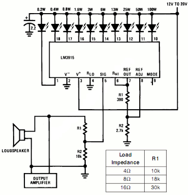
This is a simple schematic of audio power meter using LM3915 IC, this schematic can be used to measure the actual output power of your amplifier. For an audio engineer, this schematic Seems to be very helpful, especially for checking of sound system installation and field testing. Due to its logarithmic scale, the wide range of audio output with only ten scales cans Also be measured. If you take an attention to the pin number 5 of the LM3915, see That you will from the input is not yet Rectified. At this input pin, the negative swing will from the present. However, it is harmless since the current is limited by R1, the LM3915 earnest therefore respond only to positive cycle.
Note:
When the speaker resistance is 4Ω, then, make R1=10kΩ, if the resistance of speaker is 8Ω, make R1=8kΩ, and if the resistance of speaker is 16Ω, make R1=30kΩ.
The absence of peak detector or the detector will of averages give the circuit a fast reading of instantenous power, and this Gives us insight of both average and peak condition. For more readable peak or average mesurement, you cans use peak or average detector circuit.
source : national semiconductor application notes

0 Response to "Power Meter Schematic For Audio Amplifier"
Post a Comment