loading...
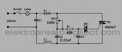
Dimmers circuit useful to control the lighting of a lamp level (brightness control) by regulating voltage Vrms (root mean square voltage). Most Interior or Lighting Design Consultant must include dimmers on each of their design, because their system with dimmers can regulate mood and color of a room with more perfect. dimmer circuit graph
This circuit is typical of a high-end leading-edge dimmers. C1 and L1 are for RF interference suppression. The circuit operates by utilising the phase shift created by VR1, C2, R1 and C3. This network delays the signal applied to DB1 (a bidirectional breakdown diode called a DIAC). When the voltage exceeds the 30V (typical) breakdown voltage of the DIAC, it Conducts fully and the charge in C3 is used to trigger the TRIAC. Once triggered, the triac will conduct fully until the current falls to near zero, at which time it turns off again. This process is repeated for every half-cycle of the mains voltage. The delay, turn-on and turn-off points are visible and indicated in the graph above.
Leading edge dimmers must never be used with a capacitive load (most electronic ballast circuits), because the very fast rise time of the voltage causes extremely high instantaneous current flow into the capacitor. Inductive loads (such as conventional iron-core transformers) are quite safe, since the inductance limits the rise time of the current to safe values.
Leading edge dimmers must never be used with a capacitive load (most electronic ballast circuits), because the very fast rise time of the voltage causes extremely high instantaneous current flow into the capacitor. Inductive loads (such as conventional iron-core transformers) are quite safe, since the inductance limits the rise time of the current to safe values.

0 Response to "Rangkaian Dimmer (Pengatur Contras Lampu 220V)"
Post a Comment