loading...
Rangkaian Booster TV
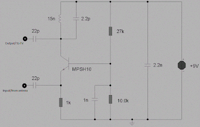
This is circuit that can be used to strengthen the RF signals from a television antenna work at UHF frequencies in the range 450-800MHz. It has a gain of around 10dB and is suitable for boosting weak TV signals
This is circuit that can be used to strengthen the RF signals from a television antenna work at UHF frequencies in the range 450-800MHz. It has a gain of around 10dB and is suitable for boosting weak TV signals
The tuned circuit comprising the 15nH inductor and 2.2pF capacitor resonate in the center of the UHF band. The 2.2pF capacitor may be Exchanged for a 4.7pF or a Trimmer capacitor of 2-6pF to improve results. The approximate frequency response is shown below. N.B. This is a simulated response using the TINA program produced by using a swept input 20uV swept over the frequency range 400-800MHz. Output was measured into a 1k source and the frequency generator has a 75ohm impedance.
The coil is half a turn of 18-20 SWG copper wire bent around a half inch drill bit. This ensures a low Q and therefore broad tuning. High frequency work requires special construction techniques to avoid instability (unwanted oscillations) caused by feedback from output to input. Veroboard is not suitable for this project as the capacitance between tracks is around 0.2pF. A better approach is to use tag-strip or a PCB. The circuitry should be enclosed in a metal case and a screen made between input and output. As the transistor is used in common base mode, its low input impedance is a good match for 50-75 ohm coax cable, whilst at the same time providing full voltage gain to the upper frequency limit of the device. The 15nH inductor load, having almost a short circuit impedance at DC, has an impedance of 56ohms at 600MHz. This inductance and 2.2pF capacitor form a tank circuit at the transistors collector, providing maximum gain at resonance.
The coil is half a turn of 18-20 SWG copper wire bent around a half inch drill bit. This ensures a low Q and therefore broad tuning. High frequency work requires special construction techniques to avoid instability (unwanted oscillations) caused by feedback from output to input. Veroboard is not suitable for this project as the capacitance between tracks is around 0.2pF. A better approach is to use tag-strip or a PCB. The circuitry should be enclosed in a metal case and a screen made between input and output. As the transistor is used in common base mode, its low input impedance is a good match for 50-75 ohm coax cable, whilst at the same time providing full voltage gain to the upper frequency limit of the device. The 15nH inductor load, having almost a short circuit impedance at DC, has an impedance of 56ohms at 600MHz. This inductance and 2.2pF capacitor form a tank circuit at the transistors collector, providing maximum gain at resonance.

0 Response to "Rangkaian Booster TV Sederhana"
Post a Comment