loading...
Gerbang Logika|Logic gate is the basic formation of a digital system. Logic gate operate with binary numbers, so that is also called binary logic gate. Voltage used in the logic gate is HIGH or LOW. Voltage 1 means high, while the low voltage means 0.
1. AND logic gate
AND gate is used to generate logic 1 if all inputs have a logic 1, if not it will be generated logic 0
Gambar Gerbang Logika AND
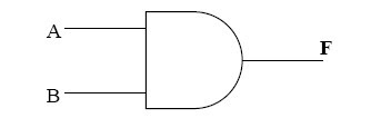
AND truth table

Statement for the Boolean AND Gate
A. B = Y (A and B is the same as the Y)
2. NAND Logic gate (Not AND)
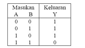
NAND gate will have a 0 output when all inputs to the logic 1. vice versa if there is a logic 0 on any input on the NAND gate, the output value 1.
Gambar Gerbang Logika NAND
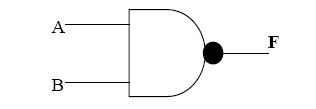
NAND truth table
3. Or logic gate
OR gate will output 1 if one of the entries on condition 1. if the desired output value 0, then all entries must be in a state of 0.
Gambar Gerbang Logika OR
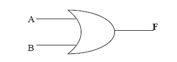
Or truth table

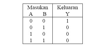
4. NOR Logic gate
NOR gate will output 0 if one of the masukannya
condition 1. if the desired output value 1, then all must be in circumstances masukannya 0.
Gambar Gerbang Logika NOR

NOR truth table
5. NOR Logic gate
XOR gate (exclusive OR of the word) will give the output 1 if its input have a different situation.
Gambar Gerbang Logika NOR

XOR Truth Table

5. NOT Logic gate
Not truth table

Gambar Gerbang Logika NAND

NAND truth table

3. Or logic gate
OR gate will output 1 if one of the entries on condition 1. if the desired output value 0, then all entries must be in a state of 0.
Gambar Gerbang Logika OR

Or truth table

4. NOR Logic gate
NOR gate will output 0 if one of the masukannya
condition 1. if the desired output value 1, then all must be in circumstances masukannya 0.
Gambar Gerbang Logika NOR

NOR truth table

5. NOR Logic gate
XOR gate (exclusive OR of the word) will give the output 1 if its input have a different situation.
Gambar Gerbang Logika NOR

XOR Truth Table

5. NOT Logic gate
NOT gate is a gate that has an input and output. NOT gate function as a commutator (inverter), so that the output of this gate is the inverse of its input.
Gambar. Lambang Gerbang Logika NOT

Gambar. Lambang Gerbang Logika NOT

Not truth table

0 Response to "GERBANG LOGIKA DASAR"
Post a Comment